An Introduction to Image Sharpening Tools in SAGA GIS
Contents
Purpose
The purpose of this tutorial is to introduce the concepts behind image sharpening of remotely sensed imagery and provide step-by step instructions for applying four methods using SAGA GIS software. In addition, this tutorial will aim to expand on the basic information and techniques presented.
Note: This tutorial assumes the user has some general knowledge in the field of remote sensing. Introductory information can be found online, and a recommended (detailed) text is John R. Jensen’s “Remote Sensing of the Environment: and Earth Resource Perspective”.
Introduction
SAGA GIS
Remote Sensing Image Sharpening
What is image sharpening?
Image sharpening is a method that has developed out of one of the balancing acts inherent to remotely sensed imagery: the trade-off between spectral resolution and spatial resolution.
Multispectral imagery sensors record detailed information in several spectral bands (red, green , blue, near-infrared, etc.), but at the cost of reduced spatial resolution. For example, the Landsat-series of satellites multispectral channels have a spatial resolution of 30 metres. In comparison, panchromatic imagery sensors record all spectral information in one band, allowing it to collect more spatial details (increased spatial resolution) at the cost of spectral information (ex: panchromatic imagery is in greyscale, not colour). For example, the Orbview3 satellite collects panchromatic images at a 1 metre spatial resolution.
Image sharpening is designed to combine the best of both worlds: multispectral imagery with high spectral resolution (colour, near-infrared, etc.) but lower spatial resolution, and panchromatic imagery with low spectral resolution (greyscale) but higher spectral resolution into one image with both high spectral and spatial resolution.
Applications
Considerations
- Spatial Resolution
- Spectral Resolution
- Geometric and Temporal Variations
Image Sharpening tools in SAGA
- Colour Normalised Brovey Sharpening
- Colour Normalized Spectral Sharpening
- IHS Sharpening
- Principle Components Based Sharpening
Methods
Acquiring Data
The data that will be used for this analysis comes from the USGS open data portal, EarthExplorer. Datasets can be searched and viewed by anyone, but a free account is required to download datasets.
The imagery used was taken over the Ottawa, Ontario region, and the datasets are best searched by a combination of date range and place (Ottawa). These two datasets were selected because they were already in the same projected coordinate system, UTM18N.
The multispectral data set used is from Landsat-8 OLI/TIRS Level 1 imagery, taken on June 29th, 2018 (Path 16, Row 28), and has a spatial resolution of 30 metres.
The panchromatic dataset is from Orbview3 Level 1 GST imagery, taken on September 10th, 2004 and has a spatial resolution of 4 metres.
Importing images as grids
Once you have downloaded and extracted the files to a selected location, they are ready to be imported into SAGA.
Open SAGA GIS and start with an Empty startup project.
To import the images, go to “File >> Grid >> Load” and navigate to where you extracted your image.
For the Landsat scenes, we will only need three of the images provided: they will have filenames ending in _B2, _B3, and _B4, which correspond to the blue, green and red bands respectively. Hold the “Ctrl” key and select the three images, then click “Open”.
Repeat the process for the Orbview3 image; there should only be one to select this time.
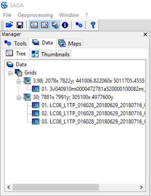
The “Data” tab of the Manager pane should look similar to the picture below. The grid system beginning in “3.98; …” is the Orbview3 panchromatic data, and the grid system beginning in “30; …” is the Landsat-8 multispectral data.
Note how no images have appeared in the right-hand pane. Before we add images to a map to view them, we will rename them in the SAGA UI to facilitate our tasks later on.
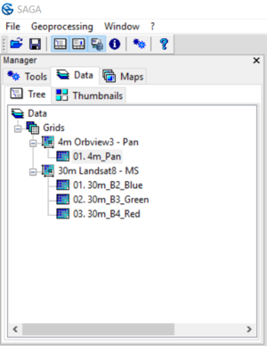
To do so, go to the “Window” tab on the menu bar at the top of the window, and make sure the “Show Object Properties” option is checked. Next, navigate to the “Data” tab in the Manager pane on the left-hand side. To rename the grid system, click on the grid system first, then click on the textbox to the right of the “Name” Entry, enter the name, and click “Apply”. The grids themselves can be renamed using the same method.
Rename the grids and grid systems to look like the following.
Now we can add our data to the map.
Begin by adding the panchromatic imagery by double clicking on the “01. 4m_Pan” grid. The default colour scheme assigned by SAGA is not what would be typically chosen to view a panchromatic image.
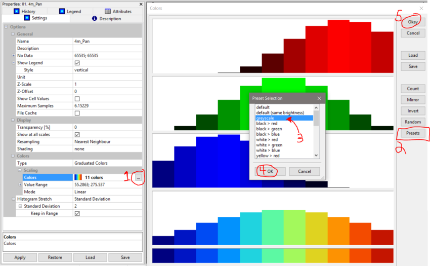
To change the colours, click on the label that says “11 colors” next to a little rainbow. Click on the 3 dots on the right to open up the “Colors” menu. In this new window, click on the “Presets” button, change to “greysclae” and click “OK” on the presets, then “Okay” in the “Colors” menu. Finally, press “Apply” in the bottom of the “Properties” pane.
You now have a greyscale image of Ottawa that you can explore.
Next we will add the Landsat-8 multispectral imagery, and view it as a true-colour RGB image.
First, double click on the “01. 30m_B2_Blue” grid, and add it to the “01. 4m_Pan” map. It will again show up using the strange SAGA default colour. Second, click on the “Type” entry, which should say “Graduated Colors”. From the drop-down menu select “RGB Composite”; note how some of the option below have changed. Next we will select the band that make up our true-colour composite. Use the menus and match the bands to the colours until they look like the image below, then click “Apply” when finished.
File:4 Landsat8MS RGBcomposite
To view, compare and explore the difference between the two images, go to the “Maps” tab in the Manager pane. Drag the “01. 03m_B2_Blue” layer below the “01. 4m_Pan” layer, so both layers are visible at once. To toggle a layer on or off, simply double click on the name of the grid.


