Clipping tutorial
From CUOSGwiki
Jump to navigationJump to search- This portion of the tutorial will provide instructions on how to create a clipping mask for the interpolation raster surface. The idea is to digitize a polygon of the lake boundary and then clip the interpolated surfaces with it, so that the interpolation does not extend onto land (which may have very different As concentrations compared to water). In order to do so, a new shapefile needs to be created. Under the ‘Layer’ tab, click on ‘New’ and then select ‘New Shapefile Layer’.
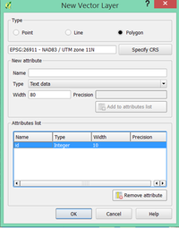
- In the ‘New Vector Layer’ window, select the option to create a ‘polygon’ in the ‘type’ field. Then specify the correct projection for the shapefile (for the purpose of this tutorial use NAD83 / UTM zone 11N). Seeing that this shapefile is just going to be used to create a clipping mask polygon, no ‘new attributes’ need to be assigned. Click 'ok'. A window will then appear which allows you to specify a filename and location to save the new shapefile. Call is ‘Clip_Polygon’, and save it.
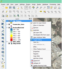
- You will now notice your new polygon shapefile in the list of layers. The next step will be digitizing a polygon of Frame Lake. Right-click on the ‘Clip_Polygon’ layer and select the ‘Toggle editing’ button.
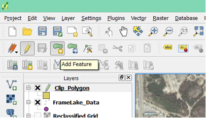
- Then click the ‘Add Feature’ button to start creating the polygon.
- Start digitizing the polygon by clicking on the edge of the lake and following the shoreline all around the lake. Use as many digitizing points as possible to ensure an accurate polygon.
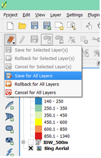
- Once you have finished digitizing your polygon, right click on the last point. A window will appear that will allow you to specify an id for the polygon, assign it a value of ‘1’. Then click 'ok'. Now that we have our Lake polygon, we can save the edits made to the shapefile and close the editor. Click on the ‘current edits’ button and select the ‘save for all layers’ button. Then right-click on the Clip_Polygon shapefile layer and click on the ‘Toggle editing’ button to stop editing the polygon.
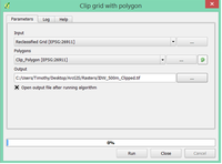
- Now we are ready to clip the ‘Reclassified grid’ using the ‘Clipping_Polygon’. To do so, search for the SAGA tool ‘Clip grid with polygon’ in the processing toolbox, and open it. In the ‘clip grid with polygon’ tool window, assign the ‘Reclassified Grid’ as the input raster layer and the ‘Clip_Polygon’ as the input polygon. Specify an output filename ‘IDW_500m_Clipped’ and click run.
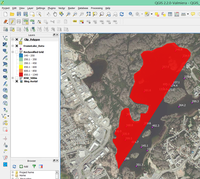
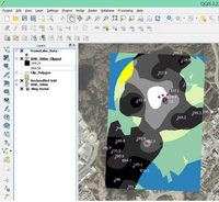
- You will notice that the reclassified grid is now clipped, but the default original greyscale colouring has returned. There is a quick way to re-symbolize the clipped raster with the appropriate colour ramp.
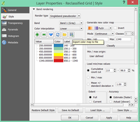
- Right-click on the ‘reclassified grid’, which still has its intact colour ramp and open the properties menu. Click on the ‘export color map file’ button, and save the text file to hard drive. Then re-open the properties menu for the ‘IDW_500m_Clipped’ raster, select the ‘style’ tab, and then pick ‘Singleband Pseudocolor for the ‘render type’. Then click on the ‘load colour map from file button’ (to the left of the ‘export color map to file’ button) and open the saved text file from the earlier step. You will now notice that your legend is back to the original format.

