Landfill Site Selection Using Spatial Multiple Criteria Evaluation in ILWIS
Contents
- 1 Introduction
- 2 Purpose
- 3 Methods
- 4 Map Layout
- 5 Conclusion
- 6 References
Introduction
Using land efficiently and in accordance with the site’s suitability for the intended purposes is a fundamental principle of sustainable development. Site suitability is a function of site conditions and other factors (environmental, socio-economic etc) . Carefully chosen selection criteria can efficiently screen the set of potential sites. Selection criteria focus on the task of choosing an appropriate and, ideally, the best site for a particular land use. This project deals with the use of Spatial Multiple Criteria Evaluation module in ILWIS software, as a decision support tool for identifying the suitable sites for landfill in the City of Ottawa.
Purpose
The goal of this project is to develop a tutorial that gives an overview of how to carryout Spatial Multiple Criteria Evaluation (SMCE) analysis in ILWIS using landfill site selection as practical example.
Methods
Spatial Multiple Criteria Evaluation
Spatial Multiple Criteria Evaluation (SMCE) is a method that assists stakeholders in decision making with respect to achieving a particular goal. It is an ideal tool for transparent group decision making, using spatial criteria, which are combined and weighted in line with the overall goal. For implementing the analysis in the City of Ottawa case study, the SMCE module of ILWIS was used. The input is a set of data that are the spatial representation of the criteria (used as factors and constraints), which are grouped, standardized and weighted in a criteria tree. The theoretical background for the multi-criteria evaluation is based on the Analytical Hierarchical Process (AHP) developed by Saaty (1980).
Generalized procedure for conducting SMCE is shown below:
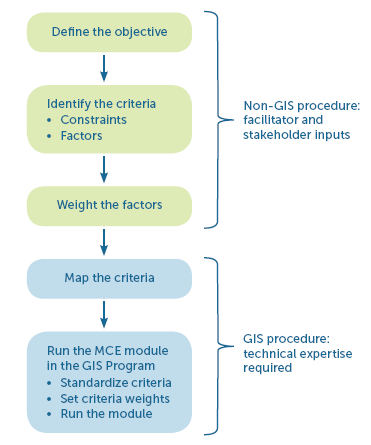 Figure 1:Generalized Procedure for conducting SMCE Analysis
Source:EL YOUNQUE Ecosystem Services
Data
About ILWIS
ILWIS is an acronym for the Integrated Land and Water Information System. It is a Geographic Information System (GIS) with Image Processing capabilities. ILWIS has been developed by the International Institute for Aerospace Survey and Earth Sciences (ITC), Enschede, The Netherlands. ILWIS 3.08.01, the most recent version is open source software and can be downloaded for free from 52 North. As a GIS package, ILWIS allows you to input, manage, analyze and present geo-graphical data. ILWIS uses vector and raster data, but most of the analysis is done in raster. This tutorial gives an overview of the steps required in carrying out SMCE analysis in ILWIS using landfill site selection as practical example.
Getting Started
Before starting the SMCE analysis, create your working folder and ensure all data needed for the exercise are in the folder.
Starting ILWIS
- Ensure that ILWIS is properly installed on your computer
- Locate ILWIS from the Program list and double click on the icon
 to launch the program.
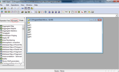
 - Once the software is initiated, ILWIS main page will open
- Use the ILWIS Navigator Tab to locate your working folder. The Navigator lists all drivers and directories.
Importing shapefiles
1) Set Data path/project environment by clicking on Navigator button to browse to the working folder
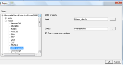
2) Click File and navigate to import and via Geospatial Data Abstraction Library (GDAL)
3) Click Vector and change the format type to ESRI shapefile
4) Click on Input tab to choose the shapefile to be imported from the working folder
5) Give Output name and click OK to open the map
6) Repeat steps 1-5 to import other data into the ILWIS environment
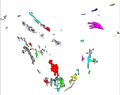
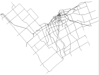
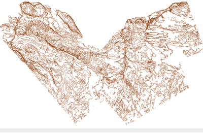
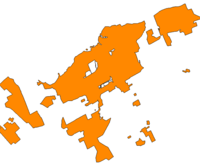
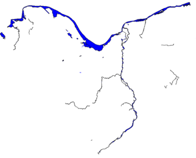
Following are the data imported to ILWIS interface
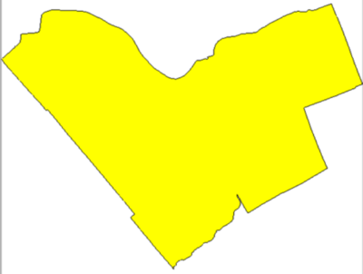 Figure 3: Boundary of City of Ottawa
Creating Coordinate System
The vector datasets for this exercise were in different coordinate systems and for a successful SMCE analysis, there is need to assign the same coordinate system and geo-referencing to all input data.
To assign coordinate system, follow the following steps:
1) Go to ILWIS main interface
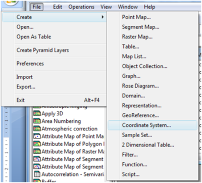
2) Click File and scroll to Create and choose Coordinate System
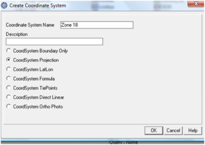
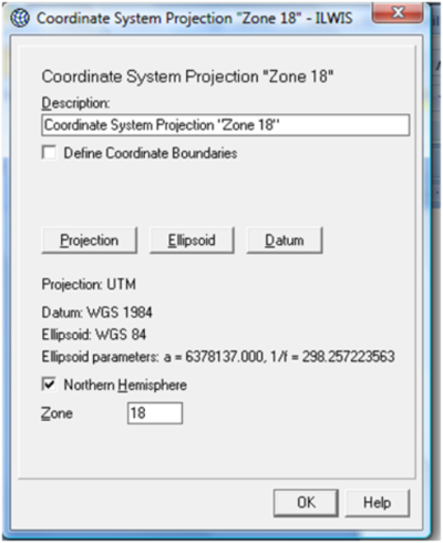
3) Give Name, select CoordSystem Projection and click OK
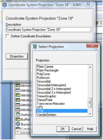
4) Select the suitable Projection and click OK
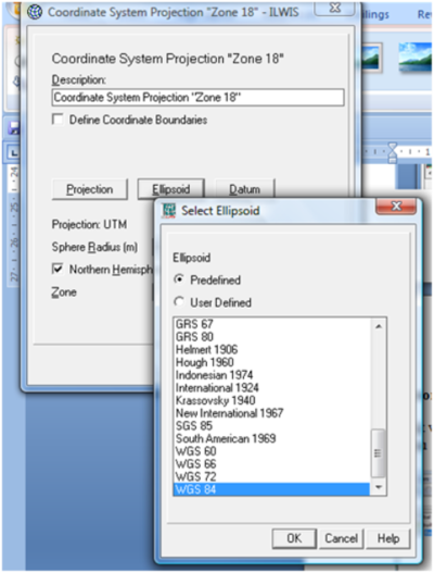
5) Click the Ellipsoid tab, select the appropriate Ellipsoid and click OK
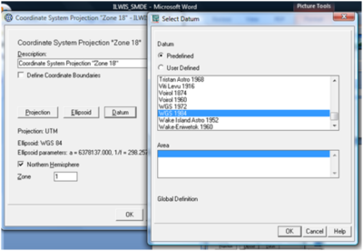
6) Click on Datum tab, select the appropriate Datum and click OK
7) Enter the suitable Zone (if necessary)
Assigning Coordinate to Vector datasets
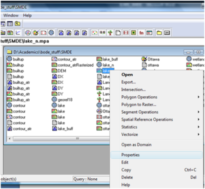
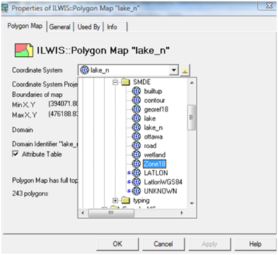
1) Right click on the vector data and choose properties
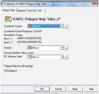
2) Change the Coordinate system to the one created earlier (Zone18)
3) Click Apply and OK
4) Repeat steps 1-3 for all the vector datasets
Vector to Raster
Since the Spatial Multiple Criteria Evaluation analysis will be done using raster data; hence there is need to convert all input data to raster. For vector to raster data conversion, follow the steps below:
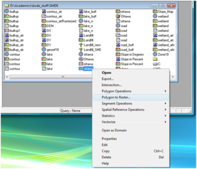
1) Click with the right mouse button on the vector map and select ‘Polygon to Raster’ from the menu
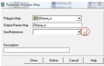
2) Click on the button beside GeoReference Tab
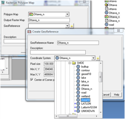
3) Give a GeoReference Name (Ottawa_n)
4) Click the Coordinate System drop down and choose coordinate system (Zone 18) created earlier
5) Click show to open the raster data
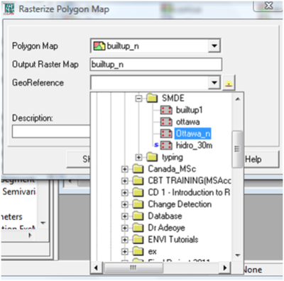
6) To ensure the all input data have the same GeoReference, use the GeoReference (Ottawa_n) created in steps 2-4 when converting other vector data to raster.
Creating Buffer
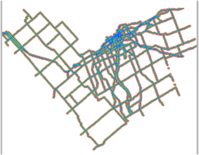
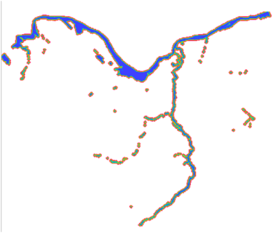
Parts of the criteria set for sitting the landfill are proximities to major roads and water-bodies; therefore buffers are to be created around major roads and water-bodies. To create buffer in ILWIS, follow the steps below:
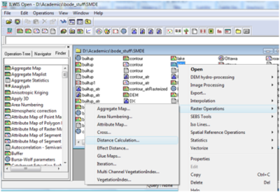
1) Right click on the raster data and scroll to Raster Operations, then choose Distance Calculation
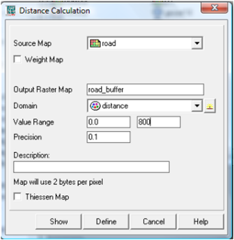
2) Give name to Output Raster Map
3) Choose distance as Domain
4) Specify distance and click show to view the map
5) Repeat the steps 1-4 for other data to be buffered.
Figures below are the results of the buffer generated:
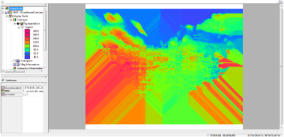
Contour to DEM
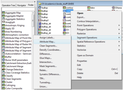
1) Right click on the contour data, Scroll to Segment Operations, then Attribute Map
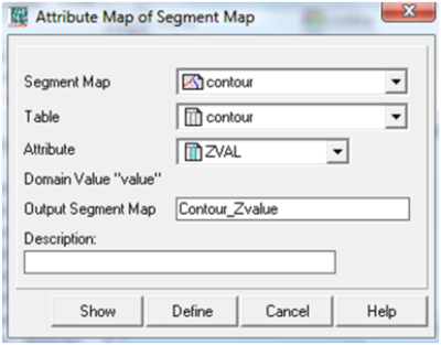
2) Change Attribute to the field that contain the Z values, then give name to Output Segment Map
3) Click show to view the map
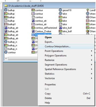
4) Right click on the newly created contour data (Contour_Zvalue) and scroll to Contour Interpolation
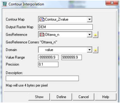
5) Give Output name (DEM), choose the GeoReference created earlier, leave Domain as value
6) Click show to view the map
DEM to Slope
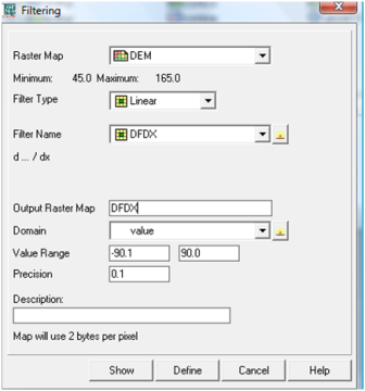
Creating DFDX and DFDY
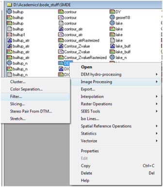
1) Right click on DEM data, choose Image Processing>Filter
2) Choose Linear as Filter Type and Filter name to DFDX
3) Give Output name and click show to view the map
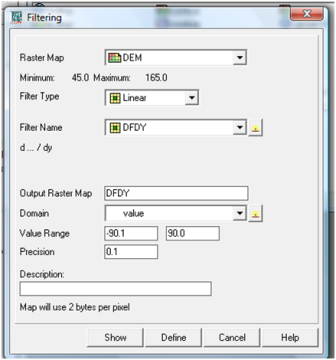
4) Repeat the same process to create DFDY
Creating Slope
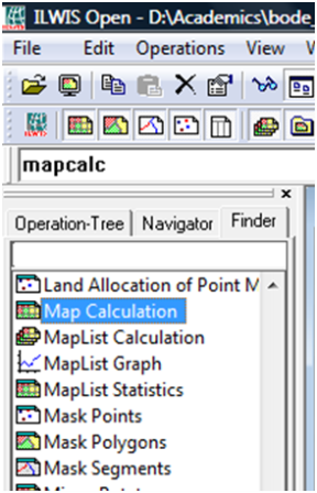
1) From the Finder Table of Content, double click Map Calculation
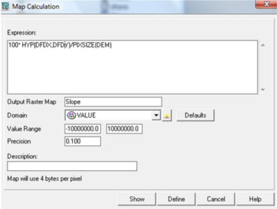
2) Type this formula: 100*HYP (DX, DY)/PIXSIZE (DEM) into the Expression Space
Note: Change DX, DY and DEM using your own data
3) Give Output name and choose value as Domain
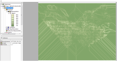
4) Click Show to view the map
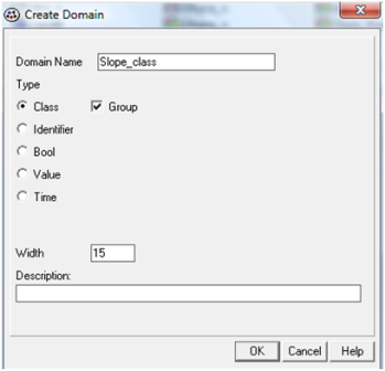
Creating Domain for Slope Classification
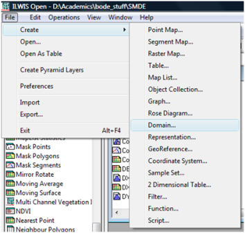
1) Click File, then Create and click on Domain
2) Give Domain Name, Check Class and Group
3) Click Ok to Continue
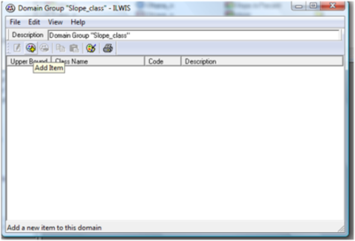
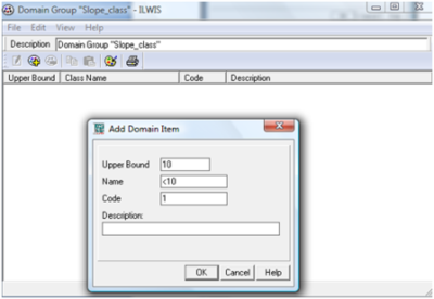
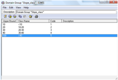
4) Click on add Item to add all classes
Combining Slope with Domain
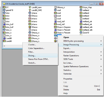
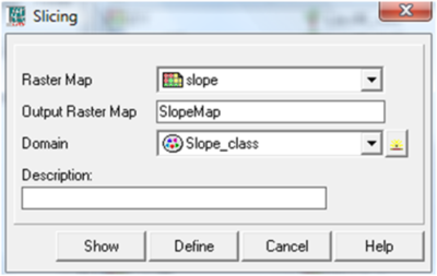
1) Right click on the Slope data, Go to Image Processing and Click on Slicing
2) Give Output Name and Choose Domain created earlier as Domain (Slope_class)
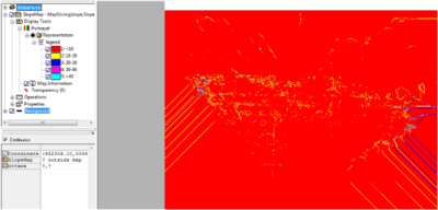
3) Click Show to view the Slope Classification Map
Spatial Multi-Criteria Evaluation Analysis
Getting Started with SMCE
1) From the Operation Tree, double click on Spatial Multi-Criteria Evaluation
2) Both the Problem Analysis and Decision Making modules will be used to find the suitable Landfill sites
3) Select on Problem Analysis and click OK to open the SMCE workspace
4) Click File>Save to save the SMCE project
5) Double click on New Goal to rename it and click on ‘filename given’ to give output name
Adding factors and constraints data
1) Click on insert Spatial Factor icon or click Edit>Insert>Spatial Factor to inset all 'Factors' data
2) Click on Insert Spatial Constraint icon or click Edit>Insert>Spatial Constraint to insert all 'Constraints' data

